2.2 3D Scanning: Potential and Challenges
This unit covers one of the methods for 3D recording; laser scanning. It will discuss the different types of 3D scanning and will explore through examples and case studies the potential and challenges of the method.
2.2.2 3D Scanning: Types and Uses
|
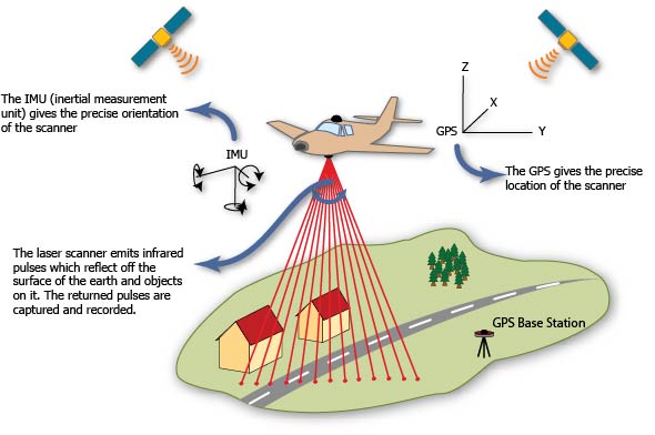
Schematic Representation of Airborne Laser Scanning principles of operation. Click image to enlarge. http://gmv.cast.uark.edu/scanning-2/airborne-laser-scanning/
|
3D scanners operate under three principles: triangulation, time of flight, and phase comparison:
Triangulation
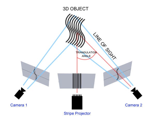
Triangulation scanners calculate the three dimensional properties of an object/feature by triangulating the position of the laser or of the pattern of light emitted by the scanner. More specifically, since the distance between the laser source and the sensor of the scanner as well as the angle between the laser and the sensor are known (based on specifications during the manufacturing process), the device can calculate the angle of the laser as it is returning to the sensor. This information is consequently used to calculate the distance from the source of laser to the surface of the object. Not only laser scanners but also structured light scanners work under the same principle. In this case, instead of a laser light, the scanner emit a linear pattern (grid, stripes) onto the object. By examining the edges of the projected pattern, the device can calculate the distance from the scanner to the object's surface. Triangulation scanners are in most cases portable since they are handheld, mounted on tripods or part of articulating arms. Structured light scanners are also portable although they tend to be less portable in relation to triangulation scanners. However, they may be more accurate by capturing higher resolution and producing less digital noise. In both cases, depending on the nature of the object scanned, special preparation may be required (e.g. to make it less reflective).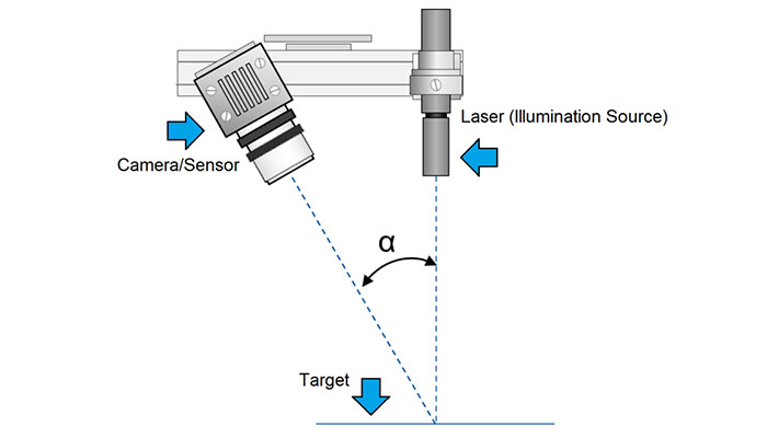 |
 |
|
Schematic Representation of the principle of operation of a triangulation scanner. Click image to enlarge. (https://www.movimed.com/knowledgebase/what-is-laser-triangulation/) |
Schematic Representation of the principle of operation of a structure light scanner. Click image to enlarge (Hesam Hamidi, Copenhagen fab lab, Denmark, https://www.opensourceimaging.org/ project/structured-light-3d-scanner/) |
Time of Flight
As the phrase time of flight indicates, laser scanners capture three-dimensional information by calculating the time that it takes for a laser pulse to return to the sensor after it hits an object. Since the speed of laser pulse is known (as part of the manufacturing process) the distance is calculated by multiplying the constant for the speed of light by the time it takes for the laser to return divided by two. Time of flight scanners are far more expensive than triangulation scanners as they can cover a much larger range (from under a metre to over a kilometre for airborne applications) at the same time achieving accuracy from 1millimetre to a few centimetres depending on the application. Acquisition time is often longer that in triangulation scanners (also because a larger area can be covered by a single scan), while generating more digital noise that requires more time at the post-processing stage.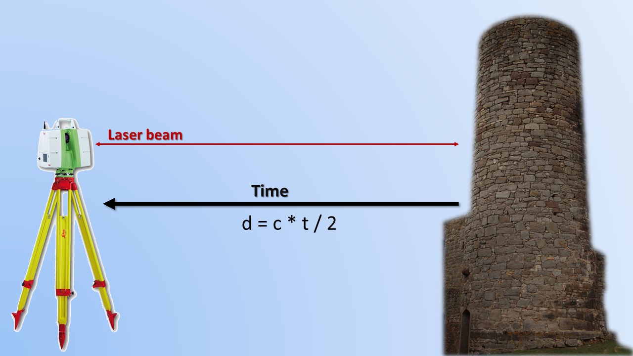 |
| Schematic representation of Time of Flight principle of operation. Click image to enlarge (image author's own) |
Phase Comparison
3D scanners that operate under the principle of phase comparison, utilise the constant light energy (laser beam) emitted by the device to measure the wavelength of the returning signal. In other words, the device compares the laser beam emitted at a certain phase shift and compare that with the phase shift of the returning signal. By doing this, the can calculate with a high degree of accuracy where (each point of) the object/ feature/ surface is located in space. Phase-based scanners, similarly to Time of Flight Scanners have a very high rate of acquisition (million points per second), however they have a medium range of capturing (up to 300m). Other than that, their characteristics are very similar to Time of Flight scanners.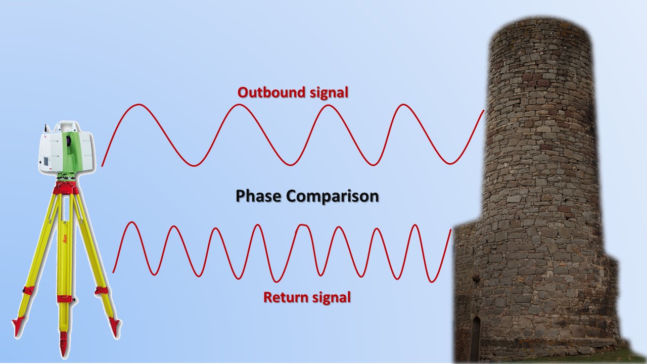 |
|
Schematic representation of Phase Comparison principle of operation. Click image to enlarge (image author's own) |
![]() Exercise: Drag & Drop the characteristics of the various types of 3D scanners (right) to the right category on the left.
Exercise: Drag & Drop the characteristics of the various types of 3D scanners (right) to the right category on the left.
Point clouds and Processing Data
As mentioned in the introductory page, laser scanners record points in space (point cloud). Each recorded point in these clouds has an x, y, z value that indicates where it is positioned in space (typically in relation to some known reference). This may be for example, in relation to the position of the 3D scanner. However, it is often useful to relate these values to a ground system of geographic coordinates (e.g. a country's national grid). The process of assigning real-world coordinates to the resulted point cloud is called georeferencing and can take two approaches: local georeferencing, in which the point cloud is related to some local control point (e.g. a particular ground feature/ point georeferenced relative to another point); and, global georeferencing, in which the point cloud is related to a site-wide or nation-wide grid.It is important to note that although point clouds include three-dimensional information, they are not 3D models. In order for this to happen, point clouds first need to be aligned or registered. This is because in most cases, you will not end up with only one scan, but you may need to conduct several so as to capture the whole area of interest. This means that the first stage of processing is to connect the point clouds. Processing software provide semi-automated ways for this, however, it is essential to have some significant overlap among the scans so it becomes easier to manually or automatically (or both) align them. It is also worth highlighting that 3D scanners also produce large volumes of noise. In 3D modelling terminology, noise indicates any captured points that you may not want as part of the final model, either because they have been wrongly produced (e.g. in case of a reflective surface) and/or because the scanner has also captured areas that you may not want to include. The latter is almost unavoidable, especially in cases where the scanning device is capable of capturing a large area but you are only interested in a smaller part. Therefore, such digital noise needs to be manually or semi-automatically removed.
However, a point cloud, even when aligned and edited for noise cannot be used further. Further modelling is needed to turn it into a mesh that will have the object's 3D properties (geometry, colour, and texture). This is accomplished by using a software that will 'connect' the high density points to produce solid geometry. It should be noted that such software also enable the cleaning and decimation of the produce point cloud and/or mesh by reducing the number of (unnecessary) points or geometric detail (triangles, faces etc.). Reducing the complexity or the noiseness of a model is particularly important especially when the model will be used for online viewing or 3D prininting. In the first case, model should be optimised so that they can render quickly in a web browser, while in the latter case, 3D printers cannot print at the resolution of a 3D model. Therefore, such optimisations can make the future uses of the 3D models more efficient. However, it is good practice to always keep/archive a model, also in its original resolution.
Software for point cloud data often come with the laser scanning devices, and therefore they are proprietary. This means that the produced file formats are (often) unique and cannot, for example, be easily transferred to another point cloud application. However, most software packages can also export text files that include the x,y,z coordinates of each point as well as the colour (Red, Green, Blue) information. Open-source software, such as MeshLab and CloudCompare, are also powerful computer programmes that provide many editing tools to clean, filter, segment, mesh, and texture point clouds, while using universal file format. One of this is called LAS and has been developed by the American Society for Photogrammetry and Remote Sensing in order to provide an open format that allows different hardware and software tools to output data in a common format. It was originally designed for aerial scanning data but it can also be used for terrestrials canning as it includes all the necessary information to smoothly transfer these from one software package to another. A similar but more flexible point cloud standard file format is called E57, developed by the American Society for Testing and Materials.
References
- Akca, D. (2012). 3d modeling of cultural heritage objects with a structured light system. Mediterranean Archaeology & Archaeometry, 12(1), 139-152. https://acikerisim.isikun.edu.tr/xmlui/handle/11729/465#sthash.FvojFPRq.dpbs
- Jones, D. (2007). 3D Laser Scanning for Heritage. United Kingdom: English Heritage Publishing. https://historicengland.org.uk/images-books/publications/3d-laser-scanning-heritage/
- Li R., Luo T., Zha H. (2010) 3D Digitization and Its Applications in Cultural Heritage. In: Ioannides M., Fellner D., Georgopoulos A., Hadjimitsis D.G. (eds) Digital Heritage. EuroMed 2010. Lecture Notes in Computer Science, vol 6436. Springer, Berlin, Heidelberg
- Opitz, R. S. (2013). An overview of airborne and terrestrial laser scanning in archaeology. In Opitz, R. S. and Cowley, D. C. (eds), Interpreting archaeological topography: airborne laser scanning, 3D data, and ground observation, occasional publication of the aerial archaeology research group, pp. 13-31. Oxbow Books.
Further Reading
- Kushwaha S.K.P. et al. (2020) 3D Digital Documentation of a Cultural Heritage Site Using Terrestrial Laser Scanner—A Case Study. In Ghosh J., da Silva I. (eds) Applications of Geomatics in Civil Engineering. Lecture Notes in Civil Engineering, vol 33. Springer.
- Opitz, R. S. and Cowley, D. C. eds (2013), Interpreting archaeological topography: airborne laser scanning, 3D data, and ground observation, occasional publication of the aerial archaeology research group. Oxbow Books. https://doi.org/10.1007/978-981-13-7067-0_3


